| 850nm PM MEMS VOA | ||||||||||||||
|
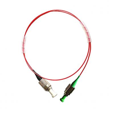
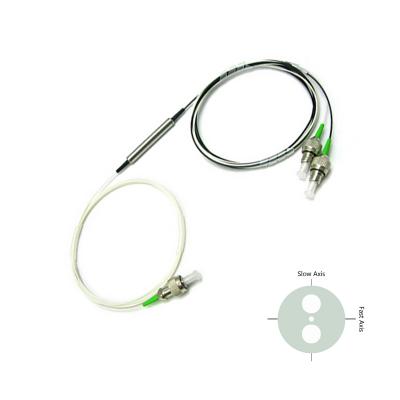
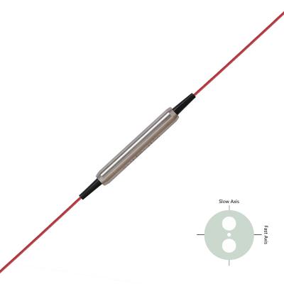
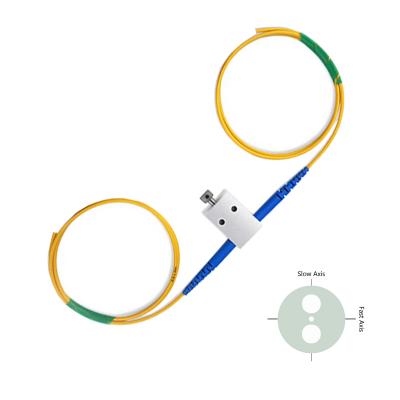
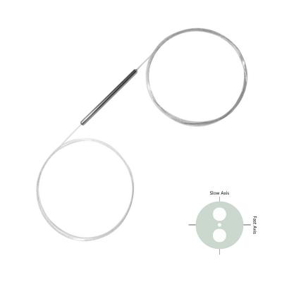
850nm Polarization Maintaining (PM) MEMS Variable Optical Attenuator (MEMS VOA) is an optoelectronic products designed for attenuating the optical power, it intergrates with a MEMS chip inside to adjust the angle of the reflection prism to achive the optical power attenuation function, it's widely used in optical power testing system, fiber line protection and optical power monitoring field. |
||||||||||||||
|
|
||||||||||||||
| Application: | Features: | |||||||||||||
|
Fiber Communication EDFA Power Protection Fiber Line Protection Testing System |
Compact Package High attenuation High responsivity High Reliability |
|||||||||||||
| Specifications: | ||||||||||||||
| Parameter | Symbol | Value | Unit | Test Condition | ||||||||||
| Center Wavelength | λ | 850 | nm | |||||||||||
| Bandwidth | BW | ±10 | nm | |||||||||||
| Min. Attenuation Range | Att. | 30 | dB | |||||||||||
| Typ. Insertion Loss | IL | 1.0 | dB | 0dB attenuation | ||||||||||
| Max. Insertion Loss | IL | 1.2 | dB | |||||||||||
| Max. Wavelength Dependent Loss | WDL | 0,8 | dB | 0dB attenuation | ||||||||||
| 2.0 | dB | 20dB attenuation | ||||||||||||
| Max. Wavelength Ripple | 0.05 | dB |
20dB attenuation, 0.4nm Bandwidth |
|||||||||||
| Min. Extinction Ratio | ER | 18 | dB | 0dB attenuation | ||||||||||
| Max. Temperature Dependent Loss | TDL | 0.2 | dB | 0dB attenuation | ||||||||||
| 1.0 | dB | 20dB attenuation | ||||||||||||
| Max. Polarization Mode Dispersion | PMD | 0.1 | ps | |||||||||||
| Max. Response Time | 3 | ms | ||||||||||||
| Driving Voltage | V | 6 or 15 | V | |||||||||||
| Min. Return Loss | RL | 45 | dB | |||||||||||
| Max. Optical Power (CW) | P | 500 | mW | |||||||||||
| Fiber Type | PM Panda fber | - | ||||||||||||
| Operating Temperatuer | T | 0 to 70 | ℃ | |||||||||||
| Storage Temperature | T | -40 to +85 | ℃ | |||||||||||
| Notice: Above specifications are tested at center wavelength without connector in room temperature @23℃. | ||||||||||||||
| For devices with connectors, IL will be 0.3dB higher, RL will be 5dB lower, ER will be 2dB lower, slow axis is default aligned to the connector key. | ||||||||||||||
|
|
||||||||||||||
| Drawing: |
|
|||||||||||||
| Pin Information: |
|
|||||||||||||
| Ordering Information (Part Number): | ||||||||||||||
| PMEV-WWW-T-A-DD-J-LL-CC | ||||||||||||||
| WWW | T | A | DD | J | LL | CC | ||||||||
| Wavelength | Attenuation Type | Working Axis | Driving Voltage | Fiber Jacket | Fiber Length | Connector | ||||||||
| 850 - 850nm | B - Bright | B - Both Axes | 06 - 6V | B - 250um Bare Fiber | 05 - 0.5m | NE - None | ||||||||
| D - Dark | Working | 15 - 15V | 9 - 900um Loose Tube | 10 - 1.0m | FA - FC/APC | |||||||||
| F - Fast Axis Blocked | 15 - 1.5m | FU - FC/UPC | ||||||||||||
| 20 - 2.0m | LA - LC/APC | |||||||||||||
| SS - Specify | LU - LC/UPC | |||||||||||||
| SA - SC/APC | ||||||||||||||
| SU - SC/UPC | ||||||||||||||
| ST - ST/UPC | ||||||||||||||
| Notification: | ||||||||||||||
|
anti-static wrist straps and grounded anti-static mats before handling the products. 2. Make sure the driving voltage is 0V before and after operating. 3. when switching on the circuit, connect ' - ' (pin2) first, then ' + ' (pin 1) and upgrade voltage slowly. when switch off the circuit, power off '+' (pin 1) first, then ' - ' (pin 2). 4. Always take anti-static measures to storage the products when not in use. |
||||||||||||||


